Do you still have your raspberry somewhere on your desk or near your TV? Great ! Because we can go to the next level and build our own arcade controller with an embedded console.
How? By putting the raspberry itself inside our arcade
stick !
First and foremost, this guide will be slightly different than the previous ones, mainly because it won’t be as detailed. I’ll provide as many information as possible on each steps, but depending on the materials and skills at disposal, you may choose a completely different solution. I also forgot to take pictures of the building processed, but provided a link to someone else’s guide that is very similar.
What we will build

This arcade controller (or stick) is basically a box, some holes, a joystick, buttons, and a raspberry pi attached together. Based on your skills, you can either build the box yourself, use metal, re-use a cheap plastic controller, or even build it with legos or transparent glass.
What do we need
- An arcade kit (buttons, cable, joystick, encoder) OR separate parts
- A Raspberry Pi
- A long HDMI cable (unless you want to play close to your screen, I picked a 3m long cable)
- A long power adapter (cheap models may not work with very long cable, so I picked a 2m long cable and checked it was compatible with a Raspberry Pi 3)
The arcade kit
This is the part where you’ll have to choose what kind of buttons you want, and balance price and quality.
Typically, there are two “families” of buttons and sticks : American ones (HAPP, and Japanese ones (Sanwa, Seimitsu…).
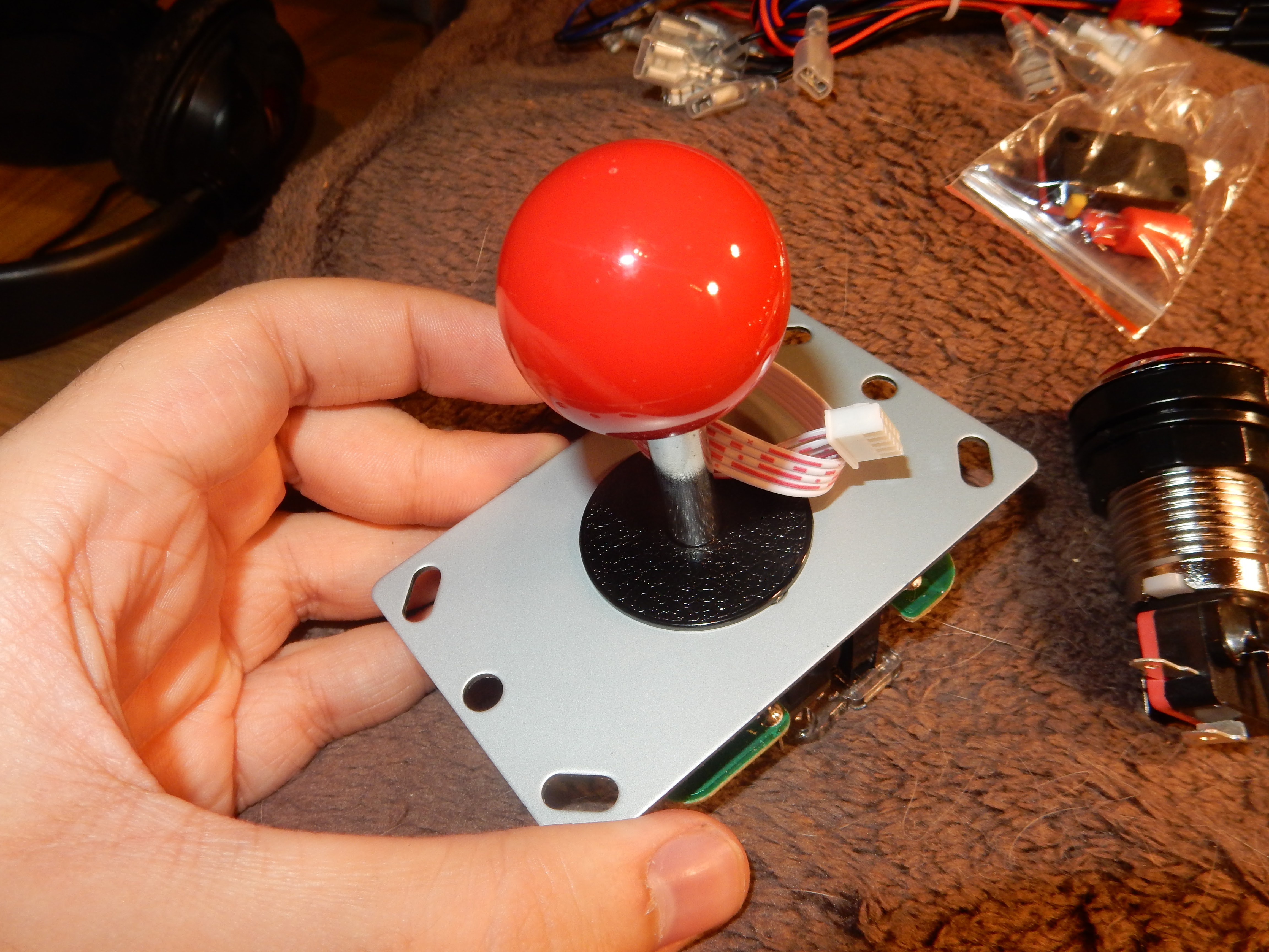
American buttons are concave, and the sticks looks
like a car shift. Japanese buttons are convex, while their sticks is literally a ball on a shaft.
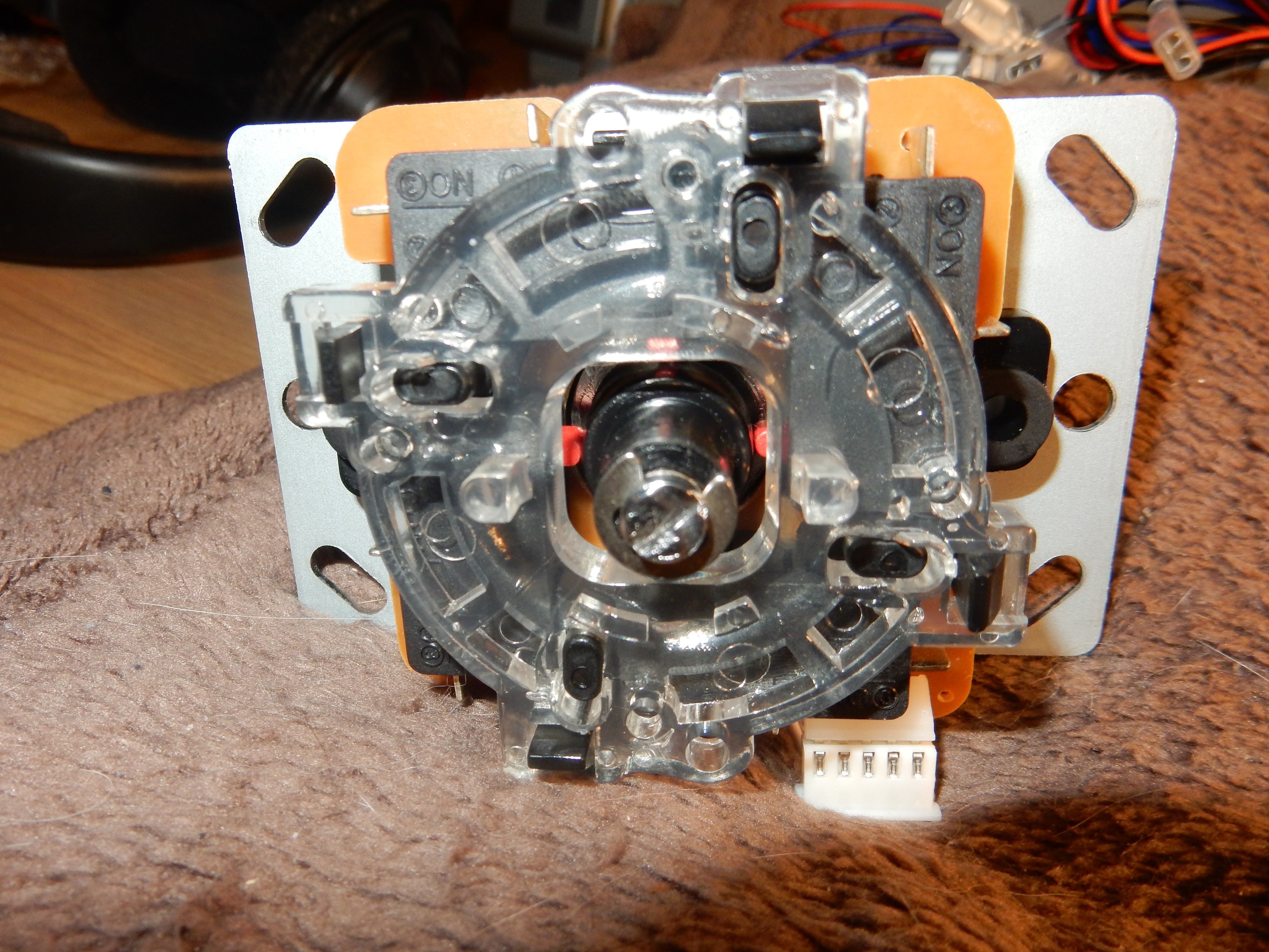
To plug all these buttons, the easiest way is to use and USB encoder. This will allow you to plug all your buttons and sticks into a small board with an USB output. In theory, you can mix and match these buttons and sticks, as long as the encoder supports both (Japanese joysticks use a single pin connector, while HAPP joysticks use four smaller connectors).
There are tons of kits available. If you want the best quality, you’ll have to buy the more expansive Sanwa, Seimitsu and HAPP parts. If, like me, you first want to try things without investing too much money, you’ll probably find what you want on Amazon or Ebay.
If you want, buttons can also come equipped with LEDs. If you stick to 5V LEDs, you should be able to power them via the USB port of your raspberry. Some kits use 12V LEDs that will require a dedicated power supply, so I strongly recommend to only buy these if you want to build a bartop cabinet instead.
I myself bought this kit on Ebay.
I was very satisfied with the quality,
relatively fast shipping (from China to Belgium), and support from the seller. Unfortunately, three of the eleven (10 and 1 spare) LEDs were not working. I contacted the seller and they sent me new LEDs that should arrive soon.

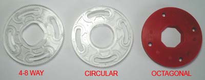
Pick a stick
You can pick any stick you want, as long as you choose a compatible USB encoder (see below). Based on your preferences, you can have a look at (or replace later) the restrictor gate (there are multiple shapes : a circle, a square, a line, an octogon…).
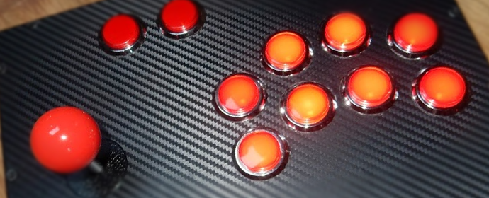
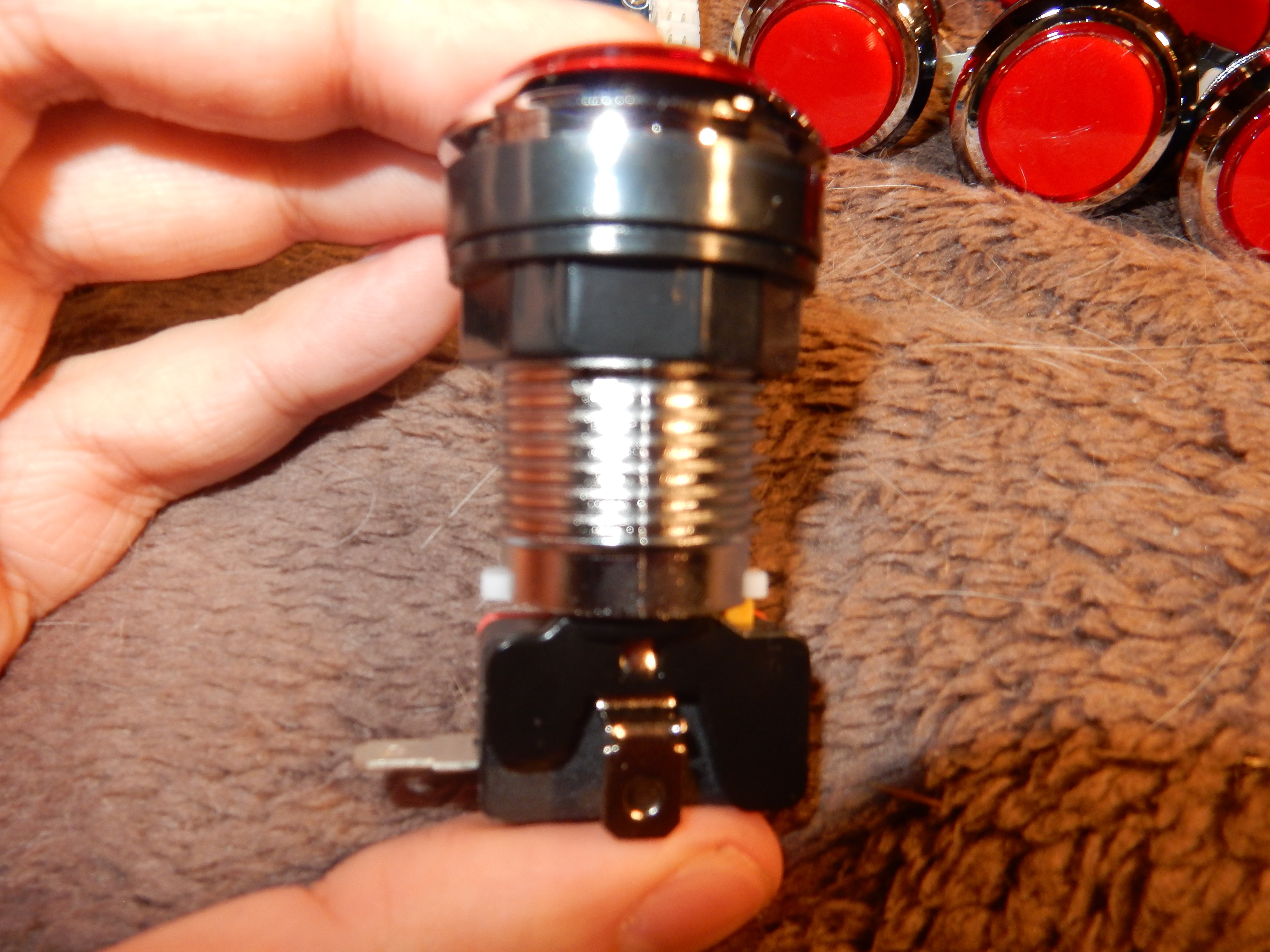
Pick buttons
Buttons also come in many shapes : concave, convex, large or small, with or without a LED. Some can be screwed in, some have to be snapped in.
If you are working with thick wood planks, ensure the button is high enough. Most buttons requires
28-30mm holes, while smaller ones usually fit into a 24mm hole (you may need to convert into inches…).
Be very careful :
- Find how many buttons you need. While SNES games only requires 8 buttons, you may need a bit more for other consoles. Most kit will include 10 buttons. This will allow you to emulate X, Y, A, B, L1, R1, L2, R2, Start and Select.
- If you are using Recalbox (my tutorial here, more information here), you’ll need another “hotkey” button. I decided to switch to Retropie instead, because they use a “Start + Select” combination instead. Or you can simply get rid of the “L2” and “R2” buttons.
I decided to go “full on bling” with these 5V led “chrome” buttons.
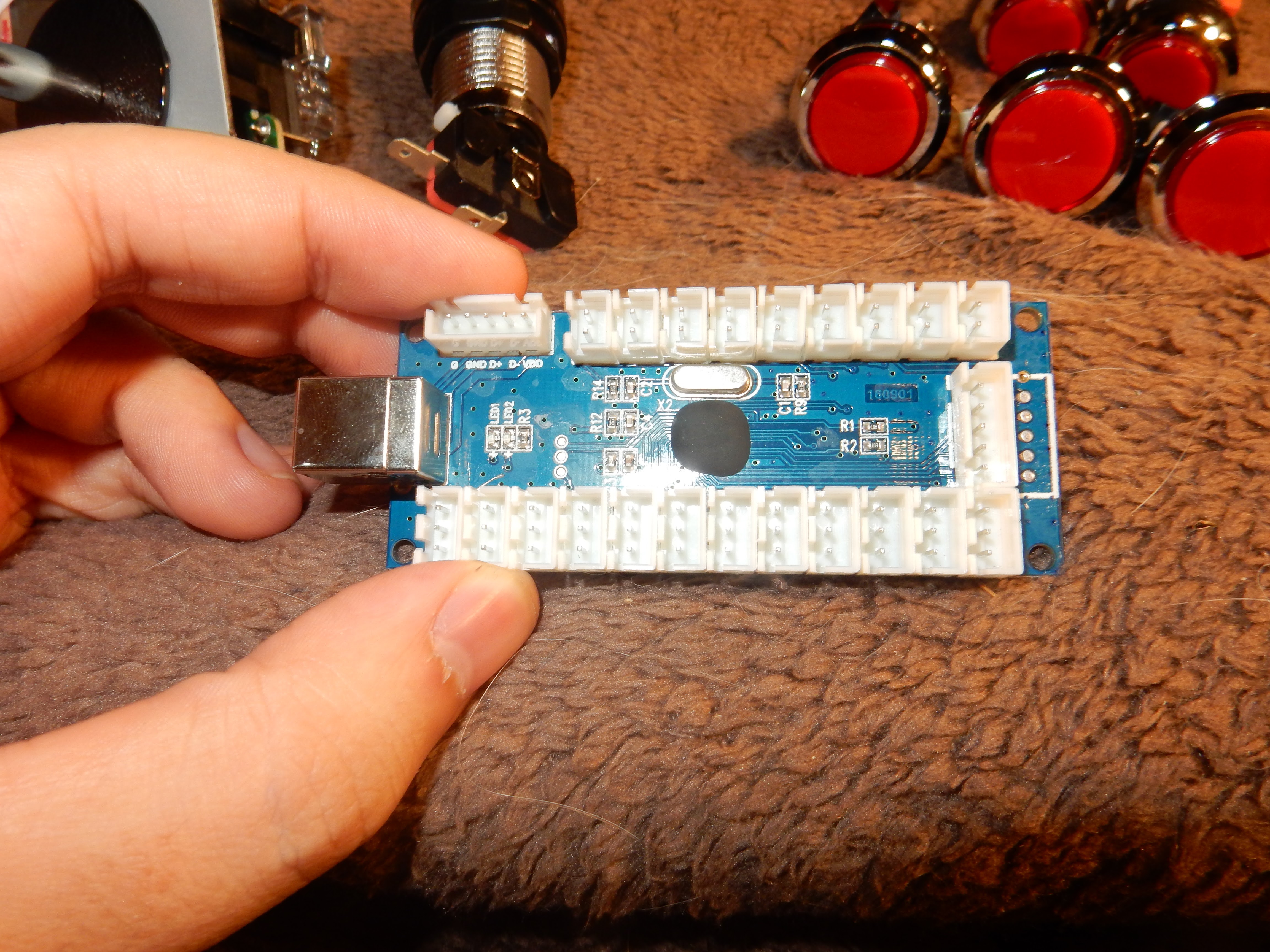
Pick an USB encoder
Unless you want to get the top quality encoder to ensure your SNES game won’t have a pico-second input delay, any encoder is fine. Double-check that the pins are compatible with your joysticks, and support enough buttons (most encoder, even
cheap ones, support up to 12 buttons, and both joystick types).
Pick one that is bundled with the proper USB cable, to make things easier.
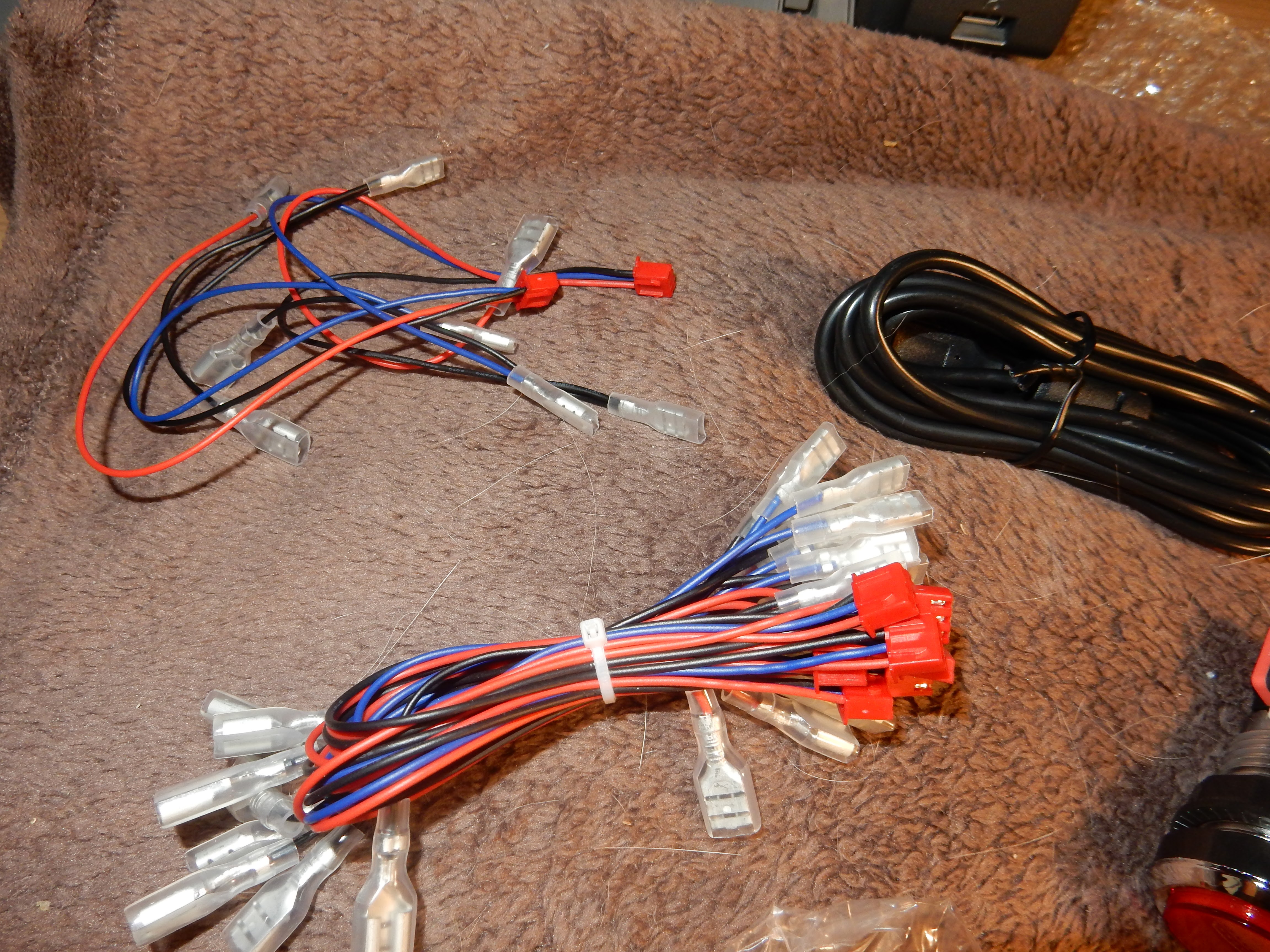
Don’t forget the cables
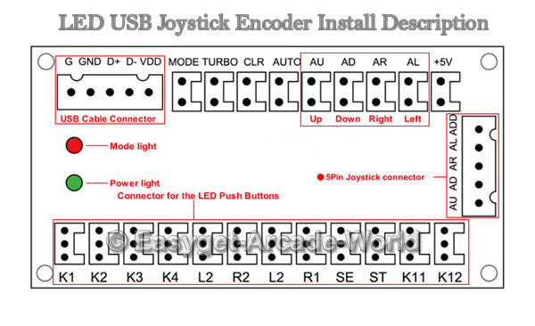
If you are buying a kit, everything should be OK. Otherwise, you’ll need to do the wirings yourself. I’ve included a schema of my encoder below. Note that basic buttons only requires two wires (5V and ground), while LED buttons will require
four wires (5V Led, 5V button, led ground, button ground).
Sometimes, the wires will all be attached to a single connector. Sometimes, you’ll have to make a daisy chain plugged to the encoder “ground”. You should find proper instructions
with your USB encoder.
Instructions
With Ikea components
If you want the easy way, someone on the internet decided to do the same thing, but using IKEA parts for the box.
You can find detailed informations on its website : http://bambooarcade.com/

“Simply” follow the instructions and you should be good.
With anything else
If you want to improvise, you’ll need to build a big-enough box and print some button layouts.
I used the same layout as the one posted in the IKEA section (http://bambooarcade.com/downloads/),
but I changed the button position slightly using Adobe Illustrator (there is a 7 days trial). You should be able to use Inkscape on Ubuntu if you want to edit the layout. Otherwise, simply use the PDFs from the download section.

If you print this layout, make sure you don’t use any zoom, custom margins or “fit to page” options. You can check that the layout is properly printed by using the included scale (there are two 125mm lines, horizontal and vertical, on the layout).
First, I used some wood plank, put the layout on top, and drilled the holes my marking the center first (use a screwdriver)
Then, I put everything together to test the buttons. You can use this HTML5 website to test that everything works.
Then, I decided to scale down the board to fit a simple A4 sheet of paper (more or less…).
Don’t worry, you can fit everything inside, even with large buttons and four cables each.
I then built a wooden box and painted it
black. I kept a hole on the side (see below) to be able to access the Raspberry Pi USB, HDMI and power plugs.
I was not very happy with the black painting, so I decided to use some vinyl overlay. At first, I wanted to design my own overlay, but I struggled to find a way to print it without ordering from the USA. I also had problems with colors,
as most of these services are related to advertising, and requires specific color profiles. So in the end, I went for a “fake carbon” overlay, such as this one.
I covered the top board, and used blades to cut the holes.
Then, I screwed back the buttons, the USB encoder, the stick, and the Raspberry Pi on the side. Be careful, if your screws are longer than the thickness of the board, you may need to use screw washers.
Finally, I attached all the cables and… Wow, that’s a mess.
As you can guess, using the provided cables is very easy, but none of them has the optimal length. In the end, I don’t care at all, because all of this will be hidden, and I don’t really want to bother with cable management.
I just had
to close back the box, screw the top board, and everything was ready for the final test.
Final steps
I plugged my HDMI cable to my TV, then to the Raspberry, and did the same with the power plug.
Retropie booted with no problem and started installing by itself. I configured each buttons, copied some games using an USB stick, and tested
right away.
I was very pleased to see that everything works as expected :)
If I had to do it again, would I follow the same steps?
Yes, probably. But there are indeed some minor things that are not perfect.
- First, the cables are a mess. It doesn’t matter, as I didn’t even bother to paint the inside of the box, and I don’t want to use custom cables.
- The buttons works fine, but are a bit hard to push. I may buy better microswitches later on, at least for the most used buttons.
- The provided USB cable is very long, because it’s supposed to be plugged to a consoler near the TV, not just next to the encoder itself. This is fine, because I let the cable outside the box, and directly into one of the USB ports.
 In theory, I should be able to unplug the controller, and plug it back to my computer, another Raspberry, or a console (but I don’t think the default button mapping will be practical). I can even plug a gamepad for specific
games, or for multiplayer games.
In theory, I should be able to unplug the controller, and plug it back to my computer, another Raspberry, or a console (but I don’t think the default button mapping will be practical). I can even plug a gamepad for specific
games, or for multiplayer games. - The box is not perfect, but I’m very happy with the final size and weight.
- I could have used plexiglass on top of the vinyl overlay. But this works better if the top board is a bit lower than the side planks.
I hope this tutorial will help you choose the right parts and build your own arcade controller.